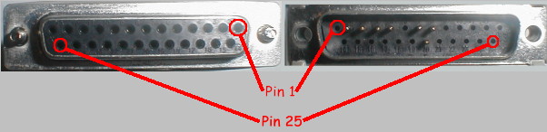
The first thing to know is how the pins in the connectors are numbers. To make life interesting, the numbering convention is chosen so that pin 1 on the "male" connector will connect to pin 1 and the "female" connector, and so on for all pins. This means that looking at a male connector, pin 1 is in the top left corner, while looking at a female connector pin 1 is in the top right corner. The diagram below illustrates:-
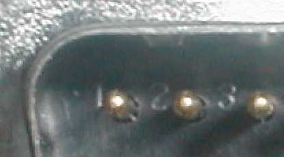
Happily, you don't need to actually remember this in any great detail. Most connectors have the pin numbers discreetly printed on them like the connector shown below:-
The pin numbering scheme is identical to that used for the 25 pin connector (see above). So pin 1 is in the top left corner of the "male" connector and the top right corner of the "female" connector.
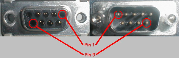
Once again, the pin numbers are usually visible (if you squint !) on the connector casing:-

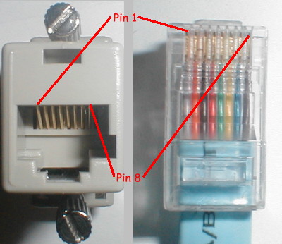
Unfortunately, this time you've got to learn them (or remember the URL for this page !) as they are not printed anywhere on the connector. Pins in RJ45 plugs and sockets are numbered as shown in the diagram:-
| Function | ||||
| DB25 | DB9 | Cisco RJ45 | Sun Console | |
| Protective Ground | 1 | |||
| TX (Transmit) | 2 | 3 | 3 | ? |
| RX (Receive) | 3 | 2 | 6 | ? |
| RTS (Request To Send) | 4 | 7 | 1 | ? |
| CTS (Clear To Send) | 5 | 8 | 8 | ? |
| DSR (Data Set Ready) | 6 | 6 | 7 | ? |
| DTR (Data Terminal Ready) | 20 | 4 | 2 | ? |
| DCD (Data Carrier Detect) | 8 | 1 | not present | ? |
| RI (Ringing Indicator) | 22 | 9 | not present | ? |
| GND (Signal Ground) | 7 | 5 | 4 & 5 | ? |
Connecting a DTE to a DCE (e.g. a PC to a modem) couldn't be any simpler. After all, that is exactly what the RS/232 specification is designed for. Quite simply, a "straight through" cable, linking pin 1 on the DTE connector to pin 1 on the DCE connector (etc.) is all that is required. Therefore, if you are using a DB25 connector, Pin 2 (TX) which is an output signal on a DTE (the PC) is linked to Pin 2 on the DCE the modem (where it is also called TX, but is an input signal).
The Cisco console kit is an interesting and clever animal. TODO: why ?!
Connecting a DTE to a DTE raises some interesting questions. Several of the RS/232 signals (Data Carrrier Detect, for example) are quite modem-specific and don't make much sense when connecting two DTE devices (e.g. two PCs) directly to each other with no DCE (modem) devices in the middle.
In order to make this work properly, a specially wired cable called a Null Modem is required. This is simply two DTE connectors wired to "fake" the missing modem signals in some meaningful way. There are a few variations on the design, depending on whether or not you are using hardware flow control and what the operating system expects to see on the interface control lines. Regardless of which variation, the objectives are:-
Here, we simply connect Tx on each side to Rx on the other, and connect the GND pins together. DSR and DCD on each side are served by connecting them both to the local DTR. Therefore, when DTR is activated (because you've just started your favourite terminal emulator), immediately and by magic DSR and DCD become active. TODO: something about RTS/CTS here
The only problem, ofcourse, is that there is no provision for hardware flow control. In this case, a software flow control mechanism (such as XON/XOFF will be necessary to avoid buffer overruns in the receiver.
This is a slightly more sophisticated version of the Null Modem. DSR and DCD are still looped to the local DTR signal, but RTS on each side is connected to CTS on the other. This allows for RTS/CTS based hardware flow control, which is the normal hardware flow control mechanism.
There is still no way for either side to detect that the transmitter on the other side is active...as long as the local DTR is active, the local DSR and DCD signals will be "faked" back
The Rolls Royce of null modems ! Here, we use DTR from each side to signal DSR and DCD of the other side. So, when you shut down your favourite terminal emulator (which hopefully isn't the hideously awful Hyperterminal !) the device you are connected to will see DCD and DSR drop. Many devices will do nothing. Others (including many UNIX hosts) will automatically shut down any active session.
You can almost get a full Null Modem using a Cisco console cable and two of the "Terminal" connectors (e.g. any combination of DB9s and "female" DB25s). This is thanks to the ingenuity of the RJ45 connector pinout and the use of the "rollover" cable. The diagram below illustrates:-
The only difficulty is that DCD is not included. Depending on what you are using the cable for, this may not be a problem (e.g. if the operating system or communications software on both sides ignore DCD). For many applications, however it is a fatal flaw. For example, it is because of this that the Cisco Null Modem cannot be used to connect a PC to a UNIX console port on some UNIX machines. Modifying the "Terminal" (DTE) connector to connect DTR to DCD internally gets around this problem without affecting anything else. I carry such a modified connector with me now to be prepared for just such an emergency (!) and it works just fine.
If you had known this was here, you wouldn't have had to read all the stuff above :-)
Use this tool to figure out the pinout you need to make a full null modem between any pair of DTE connectors.
I will add other connectors to the list as people request (or better yet, contribute !) them.