Whoever decided on the voltages to be used in RS/232 signalling had a well-developed sense of the absurd:-
| Voltage | Logic Value |
| -18v to -5v | 1 |
| -5v to +5v | (undefined) |
| +5v to +18v | 0 |
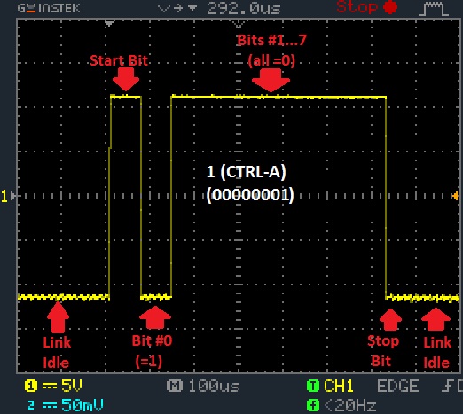
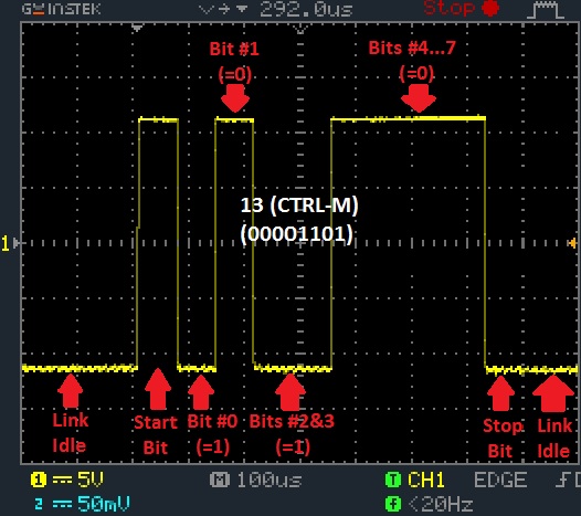
It should be apparent that the voltages representing '1' and '0' are rather counterintuitive. The 'idle' state (when there is no data being transmitted) is the logical value '1' (-18v to -5v). If you hook a voltmeter up to the TX signal of your PC when there is nothing going on, it should read around -12v.
As discussed in the previous section, each transmitted byte begins with a "start bit" which is the logical value '0' (+5v to +18v). Then the individual bits are transmitted, least significant first. Finally, a "stop bit" of logical value '1' (-18v to -5v) is sent. If there is another byte to send, the sequence simply begins again with the next start bit, otherwise the transmitter leaves the logical '1' (-18v to -5v) on the link until there is another character to transmit.
Try it for yourself. This applet demonstrates the signalling used to transmit up to 5 characters in 8-bit mode with no parity bit and one stop bit. Type the characters you want to transmit into the text box below. Move the mouse pointer over the graph for an explanation of individual bit.
These two oscilloscope screenshots show the signal on the TX pin of a PC serial port while characters are being transmitted using a terminal client:-